Bolt Selection

The first step when engineering a bolted joint is developing the total load needed between the two mating parts.
Bolted Joint – Load Considerations:
- Minimum total load necessary between mating parts.
- Vibration
- Environmental extremes
- Product lifecycle
- Factor of safety
| Thread | Class 5.8 Loads (N) | Class 8.8 Loads (N) | Class 10.9 Loads (N) | Class 12.9 Loads (N) |
| Proof | Clamp | Proof | Clamp | Proof | Clamp | Proof | Clamp |
| M3 | 1,910 | 1,430 | 2,290 | 2,910 | 4,180 | 3,140 | 4,880 | 3,660 |
| M3.5 | 2,580 | 1,940 | 3,940 | 2,960 | 5,630 | 4,220 | 6,580 | 4,490 |
| M4 | 3,340 | 2,500 | 5,100 | 3,850 | 7,290 | 5,450 | 8,520 | 6,400 |
| M5 | 5,400 | 4,050 | 8,230 | 6,150 | 11,800 | 8,850 | 13,800 | 10,350 |
| M6 | 7,640 | 5,750 | 11,600 | 8,700 | 16,700 | 12,550 | 19,500 | 14,650 |
| M8 x 1.00 | 14,900 | 11,200 | 22,700 | 17,000 | 32,500 | 24,400 | 38,000 | 28,500 |
| M8 x 1.50 | 13,900 | 10,400 | 21,200 | 15,900 | 30,400 | 22,800 | 35,500 | 26,600 |
| M10 x 1.00 | 24,500 | 18,400 | 37,400 | 28,100 | 53,500 | 40,100 | 62,700 | 47,000 |
| M10 x 1.25 | 23,300 | 17,500 | 35,500 | 26,600 | 50,800 | 38,100 | 59,400 | 44,600 |
| M10 x 1.50 | 22,000 | 16,500 | 33,700 | 25,300 | 48,100 | 36,100 | 56,300 | 42,200 |
| M12 x 1.25 | 35,000 | 26,300 | 53,400 | 40,100 | 76,400 | 57,300 | 89,300 | 67,000 |
| M12 x 1.50 | 33,500 | 25,100 | 51,100 | 38,300 | 73,100 | 54,800 | 85,500 | 64,100 |
| M12 x 1.75 | 32,000 | 24,000 | 48,900 | 36,700 | 70,000 | 52,500 | 81,800 | 61,400 |
- Proof load represents bolt failure
- Clamp load is 75% of proof load – do not exceed when engineering a bolt joint
- Total joint strength is the addition of each bolt joint
Engineer the bolt working load to be 25% to 75% of the proof load.
Under the “Torque Specifications” tab we translate clamp load into torque.
The user has to establish realistic torque tolerances they can expect from their assembly process.
Once the total load between two mating surfaces and the total number of bolted joints has been established the bolt size, thread pitch, and bolt ISO class can be determined.
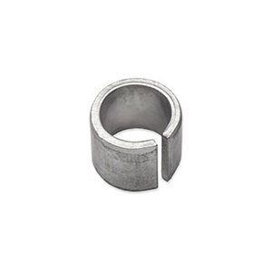
Compression Limiter Selection
The next step after selecting a bolt is to choose the correct compression limiter.
Bolted Joint – Compression Limiter Considerations:
- ISO bolt class to be used
- Press-in or over-mold
- Round or oval
- Overall length
| Insertion Type | Series | ISO 8.8 | ISO 10.9 | ISO 12.0 |
Press in - split seam
Round | CLSR | X | X | X |
Press in - split seam
| CLSO | X | | |
Over mold - closed seam
Round | CLCR | X | | |
Over mold - closed seam
Oval | CLCO | X | | |
Press in or over mold
Machined
Round | CLMR | | X | |
Press in or over mold
Machined
Headed | CLMH | | X | |
We commonly produce compression limiters engineered for special applications – both formed and machined.
A complete part number can be configured as follows:
- The press-in or over-mold options can be selected on the home page of this web site.
- The ISO bolt class and shape (round or oval) can be selected on the intermediate pages.
- The bolt diameter and compression limiter length are selected on the catalog page.
Once the complete part number is configured all important dimensions, tolerances, and corresponding hole size are listed on the catalog page.
Enter an RFQ quantity on the catalog page and submit a complete RFQ to Hubbard Spring.
Bolted Joint Considerations
In addition to bolt and compression limiter selection, the following should be considered when engineering a bolted joint:
- Compression limiter length should be slightly less than the surrounding plastic thickness. This helps clamp the plastic in place and limits its motion around the compression limiter.
- A flanged bolt or bolt / washer combination should be used with split / closed seam compression limiters.
- A standard bolt may be used with headed machined compression limiters (CLMH).
- Combinations of round / oval compression limiters are used to eliminate tolerance stack issues between mating components.
Plastic Hole Design

The following should be considered when engineering a hole for press-in compression limiter applications:
- A lead it radius on the plastic is highly recommended – this will provide smooth insertion when combined with our chamfered compression limiter.
- When a draft angle is used the taper extremes need to be within the tolerance of the recommended hole size.
Torque Specifications
The following table shows the torque that will achieve each bolt’s clamp load (75% of proof load).
All torques are listed in Newton Meters (Nm).
Actual clamp loads achieved will vary.
| Thread | Class 5.8 Torque | Class 8.8 Torque | Class 10.9 Torque | Class 12.9 Torque |
| Dry | Lube | Dry | Lube | Dry | Lube | Dry | Lube |
| M3 | 0.9 | 0.6 | 1.3 | 1.0 | 1.9 | 1.4 | 2.2 | 1.6 |
| M3.5 | 1.4 | 1.0 | 2.1 | 1.6 | 3.0 | 2.2 | 3.5 | 2.6 |
| M4 | 2.0 | 1.5 | 3.1 | 2.3 | 4.4 | 3.3 | 5.1 | 3.8 |
| M5 | 4.0 | 3.0 | 6.2 | 4.6 | 8.8 | 6.6 | 10.3 | 7.8 |
| M6 | 6.9 | 5.2 | 10.4 | 7.8 | 15.1 | 11.3 | 17.6 | 13.2 |
| M8 x 1.00 | 17.9 | 13.4 | 27.2 | 20.4 | 39.0 | 29.3 | 45.6 | 34.2 |
| M8 x 1.50 | 16.6 | 12.5 | 25.4 | 19.1 | 36.5 | 27.4 | 42.6 | 31.9 |
| M10 x 1.00 | 36.8 | 27.6 | 56.2 | 42.1 | 80.2 | 60.2 | 94.0 | 70.5 |
| M10 x 1.25 | 35.0 | 26.3 | 53.2 | 39.9 | 76.2 | 57.2 | 89.2 | 66.9 |
| M10 x 1.50 | 33.0 | 24.8 | 50.6 | 38.0 | 72.2 | 54.2 | 84.4 | 63.3 |
| M12 x 1.25 | 63.1 | 47.3 | 96.2 | 72.2 | 137.5 | 103.1 | 160.8 | 120.6 |
| M12 x 1.50 | 60.2 | 45.2 | 91.9 | 68.9 | 131.5 | 98.6 | 153.8 | 115.4 |
| M12 x 1.75 | 57.6 | 43.2 | 88.1 | 66.1 | 126.0 | 94.5 | 147.4 | 110.5 |